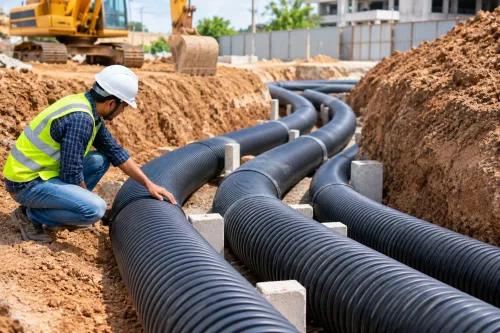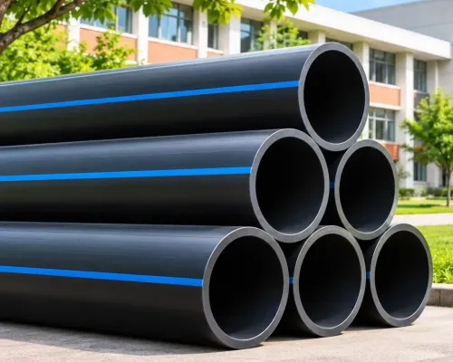
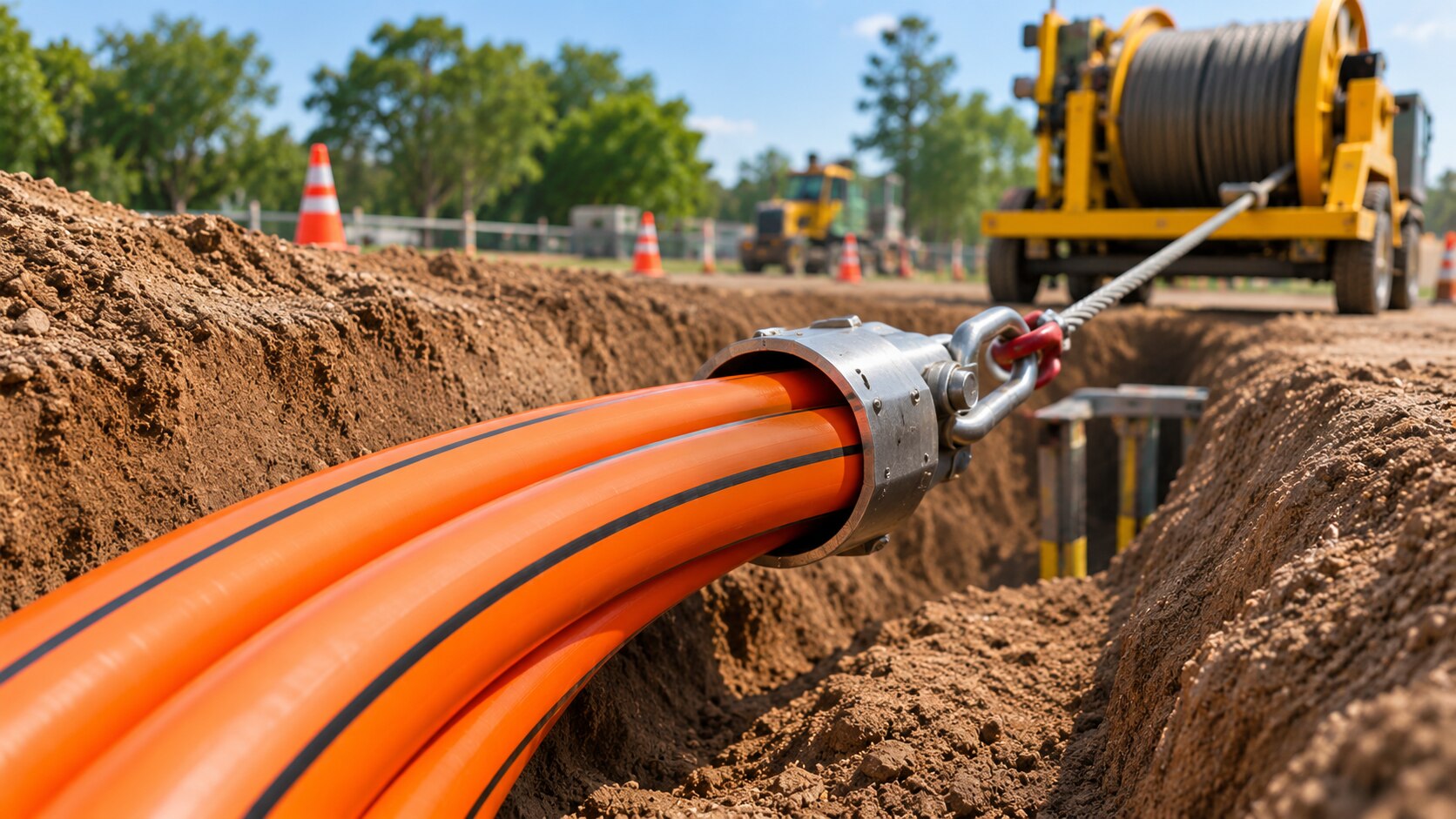
A duct’s pressure class does not tell you how hard it can be pulled through an HDD bore. You will learn how to calculate a preliminary pull force, identify the manufacturer data that controls the allowable installation load, and set field controls that protect the duct during a Nagpur utility crossing.
Key takeaways
- Separate installation pullback load from service, recovery, and damage loads.
- Calculate pull force from soil friction, bends, buoyancy, and bore geometry.
- Specify duct resin, SDR, dimensions, pullhead, swivel, and maximum allowable force.
- Record calibrated load readings and stop the pull when force rises unexpectedly.
What an HDD duct pullback limit actually measures
A pullback limit is a temporary installation limit, not a single number printed on every HDPE duct. Separate these three loads:
- Tensile force at the duct nose: the axial force needed to move the duct through the bore.
- Drag along the bore: resistance from drilling fluid, soil contact, bends, elevation changes, buoyancy, and bore-wall friction.
- Attachment load: force transferred through the pulling eye, rope, swivel, cable, pulling head, fusion transition, or other connection.
There is no universal HDPE HDD duct for pullback load limits Nagpur value. The allowable force depends on outside diameter, wall thickness or SDR, polyethylene compound, duct and drilling-fluid temperature, pulling duration, bend geometry, joints, and attachment method. A narrow pulling eye can point-load the duct even when the calculated axial force appears acceptable.
The installation limit applies for a defined pull, temperature, and duration. The installed duct’s long-term loads are different and may be governed by ring stiffness, external pressure, crushing, or buckling. PE63, PE80, PE100, pressure class, and SDR describe material or pressure-design properties; none alone is a manufacturer-rated pullback limit.
A duct can remain below its tensile limit and still fail through flattening, local point loading, buckling, or overbend damage. Check the manufacturer’s short-term allowable force and minimum bend radius for the exact duct and pulling assembly.
How to calculate required pull force before the bore
1. Start with the duct’s submerged linear weight, not its dry weight. Calculate buoyancy from the displaced drilling fluid, then establish the effective weight acting on the bore. Record duct length, fluid density, bore diameter, entry and exit angles, elevation changes, and planned curvature.
2. Build the force envelope by adding the loads identified in the bore plan:
- friction against the bore wall
- drilling-fluid drag
- elevation changes
- curvature and bend resistance
- entry and exit overbends
- a snagging allowance supported by known soil, rock, collapse, or obstruction risks
These inputs form the preliminary underground utility duct pullback loads. A long curved bore can demand far more force than a short straight bore with the same duct.
3. Check straight-pipe tension with P = A_wall × σ_allow, where A_wall = π/4 × (OD² − ID²). For a 160 mm OD duct, the idealized wall areas are about 7,238 mm² for SDR 11 and 4,712 mm² for SDR 17. At an assumed 10.3 MPa design stress, the calculated values are:
| Duct | Wall area | Calculated P |
|---|---|---|
| 160 mm SDR 11 | 7,238 mm² | 74.6 kN |
| 160 mm SDR 17 | 4,712 mm² | 48.5 kN |
4. Treat those figures as calculation examples, not rated limits. The pulling head, pulling eye, joints, bends, temperature, and installation method can govern before straight-pipe tension does.
5. Compare the calculated peak force, not the average winch reading, with the manufacturer’s allowable force and stop threshold. Confirm the exact hdpe duct pull force requirements for the product, temperature, pull duration, and assembly before drilling.
What the HDD duct specification and pulling assembly must state
The specification must identify the exact duct and the conditions behind its allowable pullback force. Do not approve a generic “HDPE duct” description; use HDD contractor duct specifications tied to one product, temperature, duration, and assembly.
Request these product documents and values:
- Polyethylene compound designation, minimum required strength, outside diameter (OD), wall thickness or SDR, and minimum inside diameter (ID)
- Allowable short-term pulling force, temperature basis, pulling duration, and safety factor used to establish that value
- Minimum bend radius and permitted pulling speed for the stated SDR, compound, duct temperature, and drilling-fluid temperature
- Manufacturer’s temperature-derating chart and the treatment of fusion joints, factory joints, repaired areas, and other joint locations
The pulling submittal must identify every load-bearing component:
- Pulling-head design, rated pulling eye, rope or cable type and rating, swivel working-load rating, and connection geometry
- Roller spacing, bend-control method, tracer wire, and any internal rope, mandrel, or pulling line
A pulling head’s capacity is not the duct’s capacity. Reject ultimate breaking load as a working-load value; require a stated working-load rating with a safety factor.
Check the actual bend radius at the expected duct and drilling-fluid temperatures. A generic rule such as 20 or 30 pipe diameters cannot replace the manufacturer’s installation-bend limit, because temperature, SDR, compound, and joint locations can govern.
How to control force during a live pullback
A rising load-cell reading is a stop signal, not an invitation to increase winch power. Control underground utility duct pullback loads by setting a conservative limit before the duct enters the bore, then investigating every unexpected change.
1. Before pulling, calibrate and zero the HDD rig’s load cell. Verify its rated capacity and calibration date, and reject the reading if the instrument is damaged or outside its calibration period.
2. Set an alarm and a stop-work threshold below the manufacturer’s allowable installation force. Use the lower limit when the bore plan, pulling attachment, temperature, or joint condition creates uncertainty.
3. Record force against chainage, time, pull speed, duct temperature, and drilling-fluid condition. These records show whether resistance is local, progressive, or linked to heating or fluid changes.
4. Watch drilling-fluid returns, pressure, and volume. Check for bore collapse, excessive cuttings, inadvertent returns, groundwater, and changes in soil or rock before treating higher force as a rig-power problem.
5. Stop when force rises unexpectedly. Do not continue pulling to find the duct’s failure point.
6. For a Nagpur crossing, account for long road crossings, congested corridors, variable soils, wet or unstable bore walls, groundwater, hot duct or drilling fluid, restricted rig access, and borehole collapse. These inputs can increase demand without creating a special local duct limit.
7. Before restarting, inspect the duct and assembly for damaged ends, fusion beads, snags, and unsealed openings. Remove the obstruction or repair the defect, then recheck the load-control settings.
How to turn the calculation into a defensible procurement decision
Approve a bid only when another engineer can reproduce its pullback decision from the submitted records. The HDD contractor duct specifications must include:
- Bore profile, entry and exit angles, planned length, radius and depth changes
- Soil investigation and drilling-fluid plan
- Calculated force envelope, allowable duct force at pulling temperature, assembly ratings, alarm and stop limits
- Pullback recording form covering chainage, time, speed, temperature, fluid condition and measured load
Compare OD and SDR together, not nominal diameter alone. At the same OD, a higher SDR has a thinner wall, smaller wall area and materially lower direct tensile capacity.
| Bid comparison | What to check | Decision effect |
|---|---|---|
| Same OD, lower SDR | Wall area and allowable tensile force | Reject a capacity comparison based on OD alone |
| Different OD and SDR | Minimum ID, wall thickness and product-specific limit | Compare the complete duct designation |
| Same duct, different assembly | Pulling head, rope, swivel, joints and bend control ratings | Use the lowest governing rating |
Accept the product only after checking the product certificate, compound designation, measured OD, wall thickness and ID, joint records, pulling-head inspection, and calibrated load-cell data.
Tatiwar Agro Industries can be considered for documented HDPE duct supply, but request the exact product-specific allowable tensile force and installation conditions—not a generic “HDPE duct” description.
That is the basis for defensible HDD duct pullback capacity Nagpur and for auditable HDD contractor duct specifications: duct, assembly, bore method and field controls documented as one system.
Related products
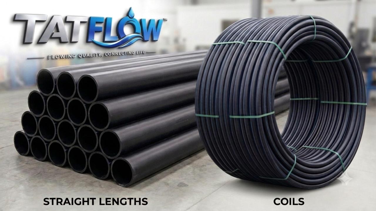 | HDPE DUCT Pipes for HDD Applications HDPE DUCT Pipes for HDD Applications Reliable HDPE Ducting for Modern Electrical Infrastructure TATFLOW HDPE Pipes for Electrical Ducting are designed to provide a reliable, durable and... View product → |
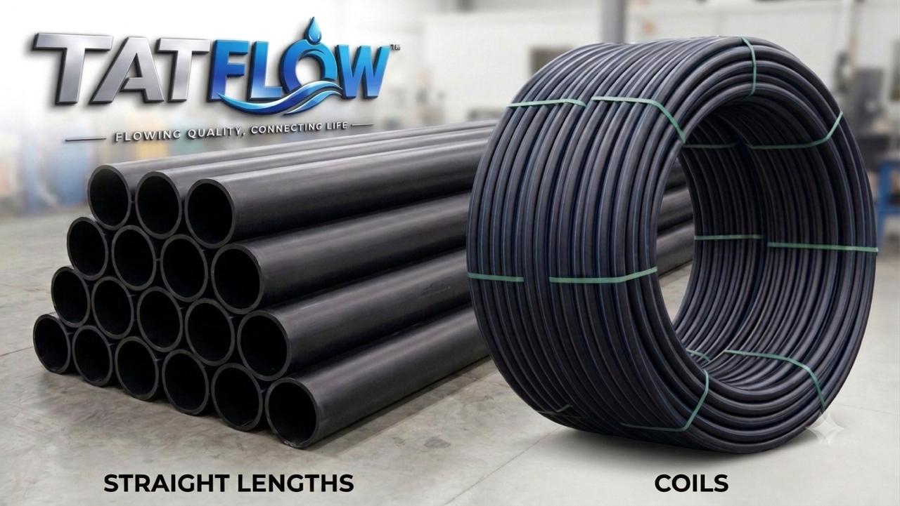 | TATFLOW HDPE Pipe for Electrical Ducting Solutions (HDD Application) TATFLOW HDPE Pipe for Electrical Ducting Solutions (HDD Application) TATFLOW HDPE Pipe for Electrical Ducting Solutions (HDD Application) Reliable HDPE Ducting for Modern Electrical Infrastructure TATFLOW HDPE Pipes... View product → |
Frequently asked questions
What does an HDPE HDD duct pullback limit measure?
It measures the maximum temporary tensile load during installation, not the duct’s long-term pressure rating or service load.
How do you calculate required HDD duct pull force?
Estimate friction and bearing along the bore, add effects from bends, entry and exit geometry, buoyancy, and the pulling assembly, then apply the project’s safety margin.
What should an HDD duct specification state?
State resin grade, outside diameter, wall thickness or SDR, length, allowable pulling load, test evidence, pullhead connection, swivel, and installation limits.
How do you control force during a live HDPE duct pullback?
Use a calibrated load cell, monitor force continuously, keep the duct aligned, control winch speed, and stop when readings exceed the approved limit or rise unexpectedly.
How can contractors make a pullback procurement decision defensible?
Compare the calculated peak force with documented allowable load, verify the complete pulling assembly, and retain drawings, calculations, certificates, and load records.
Keywords